Ethernet is one of the communication protocols that we often use in our daily life. In our offices, almost all of us connect our computers to our modems via Ethernet switches to utilize the internet.

R&D and TECHNICAL SUPPORT SUPERVISOR
So, what is this Ethernet protocol?
Ethernet is a communication protocol for connecting devices, including computers, routers, and switches on wired or wireless networks. Ethernet is the most widely used LAN (Local Area Network) connection type today, since it is not only cheaper but also more reliable in terms of operating system. So, what is the LAN connection type? A local area network (LAN) is a network that two or more computers or devices such as printers and fax machines create in an area that is not too far from each other. The main purpose of using this network area is to be able to use fast data flow between computers and peripheral devices concurrently.
Ethernet is a communication protocol with proven speed and security. Power can be transferred via Ethernet. It also supports bandwidth intensive applications such as video, storage, voice over IP transmission (VoIP) and data center consolidation.
ETHERNET STANDARDS
Classic Ethernet
It was named after the Ethernet Classic-Ethernet produced by Bob Metcalfe and his friend David Boggs in 1976. There are several standardized varieties of this Classic-Ethernet. Some of them are 10BASE-5, 10BASE-2 and 10BASE-T.
10Base-5
10BASE-5 is also called Thick-Ethernet. This is due to the fact that the coaxial cable used for data transmission is thick. If we define the 10BASE-5 standard, the number “10” is the transfer speed, the “BASE” is the type of tape used, and the number “5” is the max. segment length. Thick-Ethernet’s max. segment length is about 500 meters.
10BASE-2
10BASE-2 is also called Thin-Ethernet. The reason for this is that the coaxial cable used is much thinner than the cable used in Thick-Ethernet. If we define the 10BASE-2 standard, the number “10” is the transfer speed, the “BASE” is the type of tape used, and the number “2” is the max. segment length. Thin-Ethernet’s max. segment length is about 185m.
10BASE-T
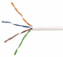
CAT 3 Twisted-Pair copper cable is used to send data. This cable is a slightly better version of the telephone cable and has a total of eight cores (four double-cores). However, only two of these four double-cores are used. One of them is for sending data and the other is for receiving data. The data is sent by encoding with the Manchester Encoding method.
Switched-Ethernet
With the development of technology, the data transfer speeds of the Ethernet standards available on the market began to become insufficient. Accordingly, new standards were developed and these new standards were combined under the name “Switched-Ethernet”. The standards of Switched-Ethernet are Fast-Ethernet, Gigabit-Ethernet, 10Gbit-Ethernet.
Fast-Ethernet

Fast-Ethernet is the first Switched-Ethernet standard that was developed. The main objective of producing Fast-Ethernet was to increase the data-rate by 10 times. In order to increase the data transfer rate so much, a more efficient coding system was developed and higher signal quality cables (CAT-3, CAT-5) were used. Some of the standards that use CAT-3 cables are 100BASE-T4, 100BASE-T and some of those that use CAT-5 are 100BASE-TX and 100BASE-FX.
As is the case in Classic-Ethernet, these names indicate the data transfer speed, the band used and the properties of the cable used. For instance, the definition of 100BASE-T4 is “100Mbps data rate, Base Band and 4 double-core Twisted Pair cables”.
Since the signal quality of CAT-5 cables is higher than those of CAT-3 cables, longer distances can be covered with CAT-5 cables, but switching to CAT-5 cable is too costly as well.
Gigabit-Ethernet

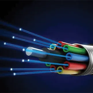
Gigabit-Ethernet is an improved version of Fast-Ethernet. The purpose of the development is to increase the data rate by 10 times. In Gigabit-Ethernet, two different cable types are used for data transmission. These are “Fiber Optic” and “Twisted Pair” cables. Examples of Gigabit standards using Fiber Optic cables are 1000BASE-SX and 1000BASE-LX, as well as 1000BASE-CX for Twisted-Pair.
All Gigabit-Ethernet standards offer a data rate of 1000 Mbps and use the base band. The extension of SX stands for Short Wavelength (LAN), while the extension of LX stands for Long Wavelength (LAN) and CX stands for Copper (Copper-LAN).
10GBit-Ethernet
The data transfer rate is 10Gbit per second. It was first produced for Fiber Optic cables and then developed for copper cables. The 10Gbit-Ethernet standards using Fiber Optic cable are 10GBASE-SR, 10GBASE-LR and 10GBASE-ER. One of the standards produced for copper cable is 10GBASE-T.
The 10GBASE-SR standard is designed for Short Range. This standard is cheap compared to other standards, but the max. distance that can be traveled is only 82 meters.
The 10GBASE-SR standard is designed for Long Range. It is slightly more expensive compared to the SR standard, but the reachable distance can be increased up to 10km.
The 10GBASE-ER standard is designed for very long distances (Extreme Long Range). Unlike the other standards, data exchange of up to 40 km can be achieved with 10GBASE-ER standard.
In the 10Gbit-Ethernet copper cable standard, the distance that can be reached varies depending on the type of cable used. Distances of up to 22 meters can be covered with CAT-5 cable, up to 55 meters with CAT-6 cable and 100 meters with CAT-7 cable.
The Way Ethernet Works
All the computer networks transmit data to be transferred over the network in “small fixed-size packets”. The advantage of this method is that the network is not kept busy for a long time by a computer that is carrying out a large file transfer. When data is sent in packets in a system, it is checked whether the cable is in use, before each packet is sent. If the cable is not in use, the package is sent, and if it is in use, it is waited for a while and tried again. If the line is still busy above a certain attempt, the package is canceled. When the package reaches the transfer destination point, the cable becomes available again for other computers on the network. Since the package are small in size, they can be sent and received by hundreds of different computers within seconds. Thus, a continuity is ensured for the users who use the network. The advantage of sending data in package is to realize error-free data transfer. The structure of the Ethernet data package is fixed. Each package contains the following four pieces of information:
- Recipient's MAC address
- Sender's MAC address
- Data
- CRC code
MAC Address
Each device connected to the Internet must have its own unique addresses in order to make a healthy data exchange. This address is also called a MAC address. The address used on any device cannot be used on another device. The MAC address is the address assigned by the device manufacturer. For instance “68-7F-74-12-34-56”; this directory is an example of a MAC address. The first six digits of the address represent the manufacturer, while the last six digits are unique identifier numbers.
CRC code
While the data is being sent in the transmission environment, it may be corrupted due to some factors. Cyclic Redundancy Check (CRC) provides detection of this corruption in case of data packets being corrupted. Ethernet data is sent in packages by dividing them into multiple parts. The order of sending the data is from “left to right”, and the order in which the bits in the byte are sent is from “the least significant bit to the most significant bit”. MAC can also send jumbo packages with a data size of more than 1500 bytes. The package structure components are as follows:

Beginning: It is added automatically by MAC. It is used for synchronization and consists of seven 0x55 numbers. On the receiving side, this part is automatically removed.
End of Beginning: It indicates the beginning of the package and contains the 0xD5 value. It is automatically added by MAC during sending, and automatically removed during receiving.
Recipient's Address: It specifies the MAC address of the recipient. Sender’s Address: It specifies the sender's MAC address.
Length/Type: It is assessed according to its value as length or type. They are assessed as “type” for
values 1536 and above, and as
“Length” for values lower than 1536. When assessed in length, this part
specifies the length of the following data. The length of the “filling” part is not included in this length. When it is assessed as a type, it indicates the type of package. For instance, 0x0800 indicates the internet protocol, while 0x0806 indicates the address resolution protocol.
Data: It contains the data to be sent and can be 0-1500 bytes long.
Filler: The length of this section varies between 0 and 46 bytes. The objective is to ensure that the package length is at least 64 bytes. If the data length is 0 bytes, the length of the filler section is 46 bytes, and if the data length is 46 bytes or higher, the length of the filler section will be 0.
FCS: The package test is calculated according to the 32-bit Cyclic Redundancy Check (CRC) method using the recipient address, sender address, type/length, data and filler sections. The receiving part applies the same method also to the incoming data to determine whether there is an error during transfer.
Ethernet connection diagram
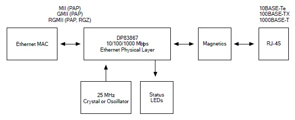
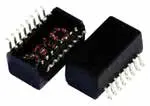
As can be seen from the diagram above, an RJ45 connector is first required for a smooth Ethernet connection. These connectors can be with internal transformers. In this way, there is no need to use an external transformer integration. If a connector with internal transformer is not used, transformer integration should be added to the system. This is indicated in the diagram as Magnetics.

PHY (Physical layer) is the physical layer of Ethernet. It is responsible for connecting the MAC layer to transmission media such as copper, fiber optics, RF. There are models that support different speeds and different interfaces. While it is optional for 10Mbps and 100Mbps devices, it is mandatory for 1Gbps devices. PHYS may also include an automatic crossover feature. With this feature, there is no need to cross the cable when the same type of devices want to connect to each other. Various integrations such as DP83867, IP101GRI, LAN8720A can be preferred as PHY.
Communication between MAC and PHY can be ensured with the following interface types.
• Media Independent Interface (MII):
It includes a 4-bit wide bus for data sending and receiving. Both time marks to the MAC are provided by PHY. The time frequency for 10Mbps Ethernet is 2.5MHz, while the time frequency for 100Mbps Ethernet is 25MHz. The TX_EN and RX_DV signs indicate that there is data on the line, and the TX_ER and RX_ER signs indicate that an error has occurred. The CRS and COL signs are used for half-duplex communication and serve to indicate conflict situations.
• Gigabit Media Independent Interface (GMII):
It includes a 8-bit wide bus for data sending and receiving. The transfer time symbol is provided by MAC, while the receiving transfer time symbol is provided by PHY. It is used for 1Gbps Ethernet and the time frequency is 125MHz. The other signs are the same as those in MII.
• Reduced Media Independent Interface (RMII):
It includes a 2-bit wide bus for data sending and receiving. The single time symbol is provided by PHY to be used for both sending to and receiving by MAC. The time frequency for 10Mbps Ethernet is 5 MHz, while the time frequency for 100Mbps Ethernet is 50MHz.
• Reduced Gigabit Media Independent Interface (RGMII):
The bus has been changed to 4 bits instead of 8 bits. The time frequency is 125MHz and both the rising and falling edges of the clock sign are used.
MAC
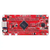
The MAC is responsible for the creation of Ethernet packages and error detection. The MAC is independent of the physical layer to which it is connected and, can be connected to any physical layer. The Nuvoton M487 series offers Ethernet MAC capability and is preferred in many projects requiring Ethernet in this regard.