
PCB DEPARTMENT MANAGER
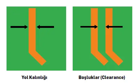
There are some questions that anyone who has just started to draw a PCB may have in mind. One of the most important aspects at this point is to draw a conductor path (Trace). What should be the thicknesses that the conductor should use when drawing the path (Trace) and the minimum Clearance that should be left between it and other conductors?
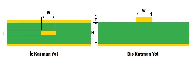
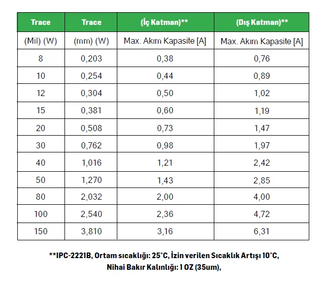
First of all, let's try to explain how you can find the carrying capacity of our conductor path. The generally accepted PCB design standard in the electronics industry is IPC-2221 (for Rigid PCBs). The reference point for current carrying capacity is Part 6.2 of the IPC-2221B standard. There, the formulas for the carrying capacities of copper conductors in the inner and outer layers are defined. To get results from these formulas, some values such as the permissible temperature increase, the length of the path, the K constant are also required.
The formula here is as follows. Detailed information can be found in the IPC-2221B standard.
Trace Width(W) = Trace Area / (Copper Thickness(T)[oz] *1.378[mph])
Trace Area [mil^2] = (Current [Ampere]/(K*(Temp.Start[°C])^B))^(1/C)
Inner Layer - K constant = 0.024, B =0.44 , C=0.725
Outer layer - K constant= 0.048, B =0.44 , C=0.725
“IPC2221 can be applied on standard boards.”
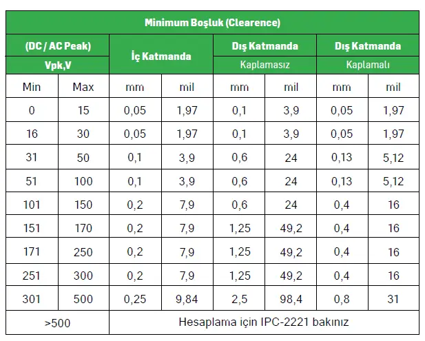
As for the minimum clearances, you can take Table IPC2221-6.1 as reference. According to the information shared here, you can set minimum isolation clearances. One should not forget that the main objective here is not PCB manufacturability, but to ensure that our circuit operates with high performance in terms of electrical isolation. There are two concepts called “Clearance” and “Creepage”. We are focusing on Clearance right now.
Initially, the reference for current carrying capacity was a standard set of graphs outlined in IPC-2221B (relationship between current, temperature rise, cross-section). Later, or after some factors and possibilities were also taken into account, it was seen that these results may not apply for every design. For this reason, a new study was conducted on the IPC-2152 standard thermal conductivity, vias, material and thickness effects on current, section copper weight and temperature, and today IPC-2152 has become the leading standard. Better results are achieved with this standard, but complex formulas and calculations appear in response. IPC-2152 may be required for complex circuits. IPC2221 can be applied on standard boards. The choice is made according to the option that you want to apply. You can make drawings using both standards, without forgetting to add a safety margin that is suitable for your circuit needs. You can quickly reach the appropriate results for your circuit by using many free calculation tools for both types on the Internet.
Another standard, IEC-60950-1, also sets safety requirements. If you want to take this as a reference, it is recommended to take a look at this standard on isolation safety here. Both standards are preferred.