Current Sensors
Magnetic Field

PROJECT DESIGN MANAGER
Magnetic field is a tool that we use to describe how the magnetic force is distributed in and around a magnetic object in space. Therefore, electrically-charged particles give rise to a magnetic force when moving. The magnetic field is usually presented in two ways;
● The magnetic field is mathematically described as a vector field. Each vector indicates the direction shown by the compass, and its length depends on the magnitude of the magnetic force.
● An alternative way to show the information contained in a vector field is to use field lines.
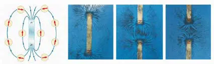
Magnetic Field and Magnetic Flux
● A magnetic field (H) is formed around a conductor, through which an electric current passes.
● If a material (magnet) with magnetism is placed in this magnetic field, the magnetic field intensity increases even more and the lines of force become more frequent.
● The additional increase in the magnetic field caused by the presence of a material is called the magnetic flux density (B).
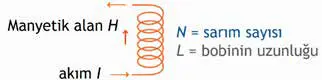
Applied Magnetic Field
The magnetic field generated by the current passing through the coil
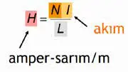
The applied magnetic field is calculated by the following formula
Magnetic Permeability(μ)
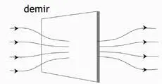
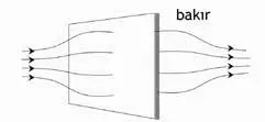
If iron is placed in a magnetic field, the field lines approach each other and the magnetic flux passing through the unit field increases.
If a substance that does not have magnetism is placed, on the other hand, the field lines move away from each other when passing through this substance, and the flux passing through the unit field decreases.
The magnetic permeability for the cavity, μ0 = 4π.10-7 Wb/A.m
B: The magnitude of the internal field strength formed in a substance exposed to a magnetic flux density H field; Tesla, T (Wb/m2 ). H and B are field vectors. They are defined not only by their sizes, but also by their directions. The relationship between magnetic field strength and flux density B=μ. The magnetic field H applied to the nucleus H induces a magnetic flux B. With an excessive increase of B, the material goes to saturation, that is, the magnetic flux does not increase any more. In other words, its permeability in saturation becomes extremely low.
Measurement of Electric Current by Hall Effect
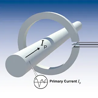
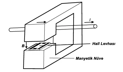
As can be seen in the figure, such a device consists of a Hall plate and a magnetic core in the air cavity. The current to be measured passes through the conductor. The magnetic field generated by the current makes the iron core magnetic, which creates a magnetic field perpendicular to the plane of the Hall plate. One of the biggest advantages of such a device is that there is no need to interrupt the circuit in order to measure the current amplitude. It is suitable for measurements between 1A-1000A. If a winding is used instead of a conductor, the air gap must become suitable in order to measure smaller currents. In this case, the maximum current that can be measured depends on the saturation effect of the magnetic material. This is because this measurement can measure DC too in addition to AC, which is unlikely with a current transformer.
AC Current Measurement with Current Transformers
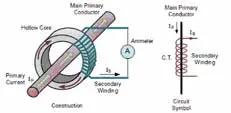
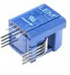
It is basically same with the transformers we know, but their outputs are seen as a current source rather than a voltage source. “Ip” is the cable carrying the primary current and usually has one cycle. “Is” secondary part, on the other hand, consists of many cycles such as 1000-2000. The current value of the equation of transformers (Np/Ns=Is/Ip) decreases in the ratio of the cycles of the secondary. When 2000A passes through the primary of the current transformer with a ratio of 1:2000, it will provide 1A output in the secondary. If we direct this current to 1r resistance, we can obtain 1V and measure the current between -2000A and 2000A with a 1W loss. The current that we will measure with a current transformer must necessarily be AC. The accuracy of these types of current sensors approaches the real (correct) values. For this reason, LEM is one of the most preferred current sensors in Türkiye and in the world. DC measurements are not carried out with transformers, and current measurement is usually carried out with Hall effect measurement techniques.
DC Current Measurement with Hall Effect
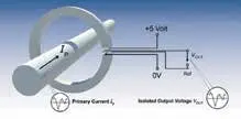
It is measured based on the intensity of the magnetic flux generated by the current, not from the current/current conversion of DC current transformers unlike the AC current transformers. The most common tool for this is Hall Effect Sensors, which measure magnetic flux. The current indicated by Ip creates a magnetic flux on the core made of magnetic material. The intensity of this flux is directly proportional to the current indicated by Ip. With these Hall effect sensors, the measured flux density is reduced to the desired voltage range, completing the measurement process. On the other hand, accuracy deviations may occur in measurement methods such as Hall effect. One of the reasons for this is that not all the magnetic field lines pass through the Hall Effect Sensor. In addition, the core’s characteristic changes depending on the temperature, and the sensor outputs change according to the applied current frequency. There are different methods to eliminate these problems.
Open Loop Current Transformers
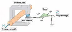
The magnetic flux intensity can be measured with Hall Effect Sensors, and then passed through a buffer with current or voltage output. It can be fed from either single or double sources, or it can be in the range of 0.5A-10kA. Since there is no feedback in Open Loop systems, it behaves as if current is passing, since the induction will continue despite the current being cut off, which makes it not very preferable.
Close Loop Current Transformers
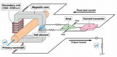
It consists of a Hall Effect Sensor and an additional winding wrapped around the transformer. Unlike the Open Loop, an attempt is made to establish equilibrium by flowing from the secondary winding in the opposite direction of the primary current so that a continuous zero flux occurs. For this, the Hall Effect Sensor is designed to scale the magnetic flux close to zero and is passed through the additional winding by converting it to output current with a differential amplifier. In this measurement, it can also be used as a voltage meter by passing the current over a low resistance. The most important point here is at point 0 of the B/H curve in the study area. Situations such as permanent magnetization or temperature shift are minimized, allowing a precise measurement to be made.